 | Noritake VFD
Administrator of Noritake Forums. If you have any issues or questions, feel free to send a message our way!
|
Hello Michael,
Thank you for your inquriy.
Based on the information you provided, the POSIFLEX #PD-2800\320 (POS terminal display) appears to use a custom controller board and firmware developped by POSIFLEX. While it is possible that POSIFLEX may have sourced a display module from us, the final product - including the 7-position DIP-switch configration and supported ESC command set - is entirely designed and controlled by POSIFLEX. So the command set and control behavior may differ from the standard Noritake VFD command specifications.
Because of this, we unfortunately do not have documentation or technical details for the command set, brightness control, screen clearing, or other functions used in this POSIFLEX model.
For accurate information, we recommend referring to POSIFLEX’s documentation or contacting their technical support team directly, as they would have the correct specifications for this product.
If you have questions about Noritake‑branded VFD modules or our standard command sets, we would be happy to assist. Please feel free to reach our local sales & technical support through our web contact form. Once submitted, your inquiry will be automatically forwarded to the appropriate local team for follow-up.
Hello Michael,
Sorry for our late response.
Could you let us know your contact info to support you directly if you need our support?
Please contact us via our contact form. Our sales engineer will support you.
https://www.noritake-elec.com/support/contact-us
Hi Everett,
Thanks for posting and sending a technical support request via our website. Our sales & customer support team contact you shortly.
Thipok,
Best Regards,
Noritake VFD
Hellp Thipok,
That is great to hear! Glad the 74HC04 solved your issue.
If you have any other questions or issues, feel free to create another thread.
Have fun!
Thank you.
According to its datasheet, the GU256x64D-7000BX display's asynchronous serial interface can accept RS-232 level input as seen below:

However, it seems your host board is communicating using CMOS level signals. Which is why you need to invert your data via software.
Assuming your host board is using 5V signals, then you need to invert your TX/RX communication signals. Afterwards, software data inversion will not be necessary. This may also eliminate the need to send an extra 0xFF data byte.
As a side note: the GU-7000 Arduino code library will automatically invert the communication level signals based on the display generation number. (7000, 7003, etc.)
Hello Stingpie,
The GU-7000 Arduino code library has not been tested with the RP2040.Therefore, there may be some nuances when using this library.
The GU-7000 Arduino code library was created a while ago, so I am unable to ask the original developer why the interface is software-based.
It seems you are flipping the command byte bits.
0x1B = 0b00011011
0xFF - 0x1B = 0xE4 = 0x11100100
Can you check your GU-7000 product number? I would like to check the display's communication polarity.
The product number is located somewhere on the PCB, usually on the back. It is formatted similar to this: GU140X32F-7000B
Hello Ian,
Have you tried disabling hex mode with the [0x1B, 0x42] byte sequence?
While in hex mode, the display interpreits 0x60 as a hexadecimal prefix. So, if hex mode is disabled, 0x60 is treated normally.
Let me know if this improves your issue at all.
Best Regards,
Noritake VFD
Hello Ian,
Have you tried disabling hex mode with the [0x1B, 0x42] byte sequence?
While in hex mode, the display interpreits 0x60 as a hexadecimal prefix. So, if hex mode is disabled, 0x60 is treated normally.
Let me know if this improves your issue at all.
Best Regards,
Noritake VFD
Hello Hofstee,
In order to properly support your fuse issue, please fill out our contact us form: https://www.noritake-elec.com/support/contact-us
Afterwards, one of our sales engineers will contact you as soon as possible.
Best Regards,
Noritake VFD
Hello Berg,
We are unable to find part number VAD3265 in our database.
Can you please verify this part number?
Best Regards,
Noritake VFD
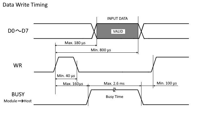
This product was discontinued more than 25 years ago, so we cannot guarantee the information on this post is accurate. However, the pin assignment info and timing chart is from our trusted technical archives.
TZ,
Happy to help!
If you have any more questions, don't hesitate to create another post or contact us via our contact form: https://www.noritake-elec.com/support/contact-us#wo-sign-in
Best Regards,
Noritake VFD
TZ,
I would recommend using the Print statement followed by the hexadecimal command generated by GTOMP in the Memory Tool map area. After saving an image to FROM2 using GTOMP, you should see information in the map area of the tool. Underneath the information for each image, a set of hexadecimal numbers are present in brackets. (For example: [1Fh 28h 66h 10h ...]) Use these values in your program macro with the Print statement to recall the image to the screen. (For example: Print &h1F, &h28. &h66, &h10 ...)
The CopyBmp function is implemented for our VFD modules.
Best Regards,
Noritake VFD
TZ,
Is your plan to use a program macro to display a couple images and then act as a slave when switching to the menu?
I would recommend you look at the "Msousi Program Macro compiler Manual". However, this document is written for our VFD modules and has not been updated for GT-CP modules. Just keep in mind that memory access addresses are different and you can use TpX and TpY to read touch data like the following code:
TpX = &h01 'Ask for coordinate data for touch #1. Not needed for single touch mode.
tx = TpX 'Save x coordinate data from variable 8
ty = TpY 'Save y coordinate data from variable 9
Regarding image recall, have you saved an image to your GT-CP module's FROM2 using GTOMP?
Best Regards,
Noritake VFD
Hello TZ,
Yes, the only way to connect to a GT-CP module using Msousi on Windows 10 is with a COM port. If you have a USB to 3.3V serial converter, that should work just fine. Otherwise, you can write program macro code in Msousi, compile and export the code as a .dat file, and use GTOMP's Memory Tool to load and run the code on your GT-CP module. If you would like a more detailed procedure on this workaround, just let me know.
GU-TFT Tool does not work on Windows 10, it was developed for Windows 7 and is not being updated anymore. GTOMP was developed as a replacement tool.
If you don't mind me asking, what application do you plan on creating with program macro?
Best Regards,
Noritake VFD
Varun,
Maybe instead of using fprintf(s,'\n'), can you send hex values 0A and 0D to the display?
Also, can you try removing the timeout and see if your module is still getting cleared?
Thank you,
Noritake VFD
Varun,
It looks like your code is sending '\n' instead of a carriage return line feed (CRLF).
Have your tried configuring your serial terminator as a carriage return line feed?
For example: s=serial('COM1','BAUDRATE',38400,'Terminator','CR/LF')
Best Regards,
Noritake VFD
Moka,
Thank you for providing your code.
I would like to clarify your exact issue.
When you execute your code, "heloo" is displayed on the screen but the screen is cleared shortly afterwards.
Additionally, when you execute the code again, you can see two "heloo" strings on the display until you turn the display off.
Is this correct?
Best Regards,
Noritake VFD
Moka,
That is quite strange behavior.
Is your matlab code only sending "Hello World" to the display? (like the code from your first post)
If not, can you send the code you are current working with?
Thank you,
Noritake VFD
Moka,
Can you explain your issue in a bit more detail?
I am having a difficult time understanding your most recent post.
Thank you,
Noritake VFD
Moka,
Can you check your signal voltage? The display module expects 5V signals.
Additionally, make sure you have common ground between your PC interface and VFD interface.
Best Regards,
Noritake VFD
Moka,
Can you check your signal voltage? The display module expects 5V signals.
Additionally, make sure you have common ground between your PC interface and VFD interface.
Best Regards,
Noritake VFD
Moka,
Be sure to check all comunication settings from your hyper terminal session. Not only baudrate, but parity as well. This module's default parity value is EVEN. However, since you cannot see the jumper configuration, it is difficult to say which parity mode is being used.
Based on your MATLAB code, you do not set any parity, so this could be the issue.
Best Regards,
Noritake VFD
Hello Moka,
Thank you for your question.
First off, could you provide your signal wiring and jumper configuration? (J0 - J4 and JA)
Thank you,
Noritake VFD
Sergey,
If this display is manufactured by Noritake, It will have the Noritake itron logo on the back side of the VFD panel like the picture below.
If it is a Noritake display, we are unable to disclose any information about custom display modules like this.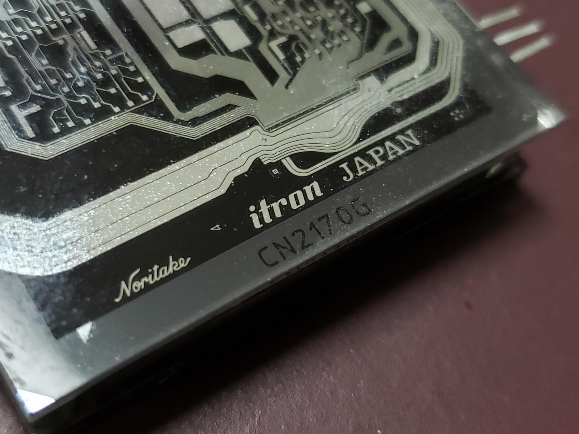
Best Regards,
Noritake VFD
Sergey,
Thank you for your question.
It looks like this is not a Noritake display module.
You may be able to get more information if you contact the PCB manufacturer's customer support team.
Best Regards,
Noritake VFD
Brad,
Great to hear!
If you have any other questions, don't hesitate to ask.
Best Regards,
Noritake VFD
Brad,
Thank you for the information.
Our GT-CP VCOM driver is not compatible with Windows 10. GT-CP modules natively support WinUSB, so you need to let Windows install this automatically.
To uninstall the VCOM driver and install WinUSB, follow this procedure:
1. Please uninstall "USB VIrtual COM port (COM4)" and "Noritake Itron Display" from your PC. Make sure to check the "Uninstall the driver software for this device" checkbox.
2. Unplug the GT-CP module from your PC.
3. Plug the GT-CP module back into your PC. The WinUSB driver should automatically install.
4. In your Device Manager, you should see the GT-CP module's product number (GTWV050C3A00PA) listed under "Universal Serial Bus devices".
If your driver installation is still not sucessful, please let us know, post a screenshot of your device manager, and we can troubleshoot this issue with you.
Best Regards,
Noritake VFD
Hello Brad,
We have replied to your other post and will continue to support you there.
Noritake VFD
Hello Brad,
Can you explain exactly how you connected your GT-CP module to your PC as well as the subsequent steps/events before you arrived at this properties window?
Also, could you post a screenshot of your device manager? (or at least the section where your GT-CP module shows up?)
Best Regards,
Noritake VFD
Hello Taichi,
My recommendation would be to change the edges of your button to be a slightly less-intense color compared to the button's main color.
For example, if you have a grey button, make the edges of the button very slightly darker to make it feel like it is fading away.
Additionally, make sure the edges of your button do not have any transparent pixels. The GT-CP module cannot render transparent pixels and makes those pixels white.
Best Regards,
Noritake VFD
Hello Taichi,
Thank you for your question.
There are a couple ways you can reduce the start-up time of your iDevTFT program.
1. Convert the images in your project to .tri format. This format loads very quickly on iDevOS. This can be done in iDevTFT by going to "USB Transfer > Create TRI image files". This will create .tri copies of your project's image files. Once the conversion is complete, make sure to change each image extension within your iDevTFT program so it is looking at the correct file.
2. If you are using multiple .mnu files to utilize different sub-programs, don't load all of the .mnu files at the start of you main program. Load the .mnu file only when you are about to use it. This will reduce the time it takes to get to your main page. This method will increase the time it takes to get to a sub-program by a few seconds, but once a .mnu file is loaded once, it stays loaded until the main program exits or the module is reset.
In summary, to reduce the start-up time of your iDevTFT program, you can:
- Convert images to .tri format.
- Don't front load your .mnu sub-programs. Only load them when needed.
I hope this information helps! If you have any more questions, don't hesistate to ask!
Best Regards,
Noritake VFD
David,
We are happy to help.
Please see the following related command information:
1. ASCII Commands are available for only Backspace (0x08), Horizontal-Tab (0x09), Line-Feed (0x0A), and Carriage-Return (0x0D).
2. Noritake Commands are available for changing thte device control mode and listed as follows;
DC1 (0x11): Character Overwrite Mode (Default Setting)
DC2 (0x12): Vertical (Text) Scroll Mode
DC3 (0x13): Horizontal (Text) Scroll Mode
These modes change the way the module behaves when text reaches the end of the display. Overwrite mode will move the cursor back to its home position and overwrite the displayed chracters. Horizontal mode will keep the cursor at the end of the display, shift the displayed characters to the left and write the new character.
Note: Since the display has a single line, The DC2 mode does not move the displayed-text up when the cursor reaches to the right-end position.
3. Cursor Position Set Commands are simple correspond the cursor location by sending 1 byte command as follows.
M0 (0x80): The cursor moves to the leftmost position
M1 (0x81): The cursor moves to the second column from the leftmost position
M2 (0x82): The cursor moves to the third column from the leftmost position
M4 (0x83): The cursor moves to the forth column from the leftmost position
continued…
M15 (0x8F): The cursor moves to the sixteenth column (the rightmost position)
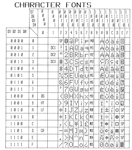
Also, please see the associated font table:
Best Regards,
Noritake VFD
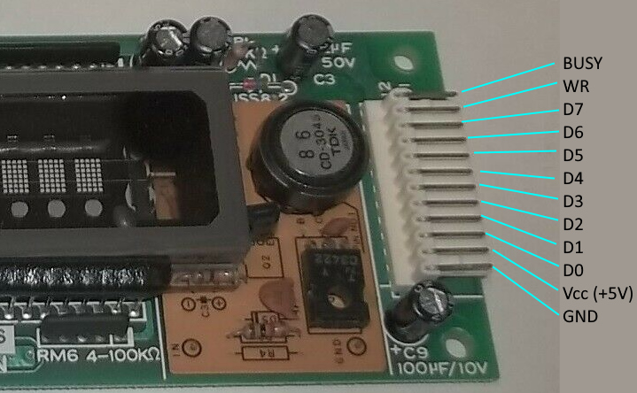
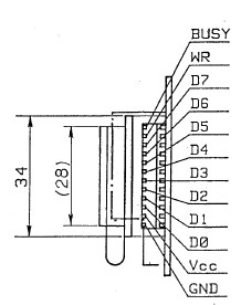
David,
For your reference, please see the following pinout image.
Hello David,
Thanks for sharing the display module image. That was not CU165ECPB-T2J and it looks more historical (older) model.
It seems the datasheet has not existed anymore even in the document archive.
But, we are looking for the data of that module and will update you when we found some helpful info.
Regards,
Noritake VFD.
Hello David,
Thank you for your post. We just replied the pin assignment info to your other post.
https://forum.noritake-elec.com/post/9645334/
If you need any further information, please fill out our inquiry form here: https://www.noritake-elec.com/about_us/contact_us.htm
Thank you,
Noritake VFD
Hello David,
Thank you for your post. We assumed that the correct part number is CU165ECPB-T2J.
However, the CU165ECPB-T2J has been discontinued more than 10 years ago, and the spec is not available on the website.
We received some information from our old document archive and got the pin assignment of the CU165ECPB-T2J as follows.
| Pin No. | Signal |
| 1 | Vcc |
| 2 | GND |
| 3 | /CS |
| 4 | CLK |
| 5 | DATA |
If you need any further information, please fill out our inquiry form here: https://www.noritake-elec.com/about_us/contact_us.htm
Thank you,
Noritake VFD
Hello Taichi,
You can stop a program macro when serial data is received with the following program macro code:
‘/////////////////////////////////////////////
‘Global Variable
RecBff = &h00 ‘ Receiving Buffer
Sub Start()
Cursor 0,0
Cls ‘Clear Screen
lp:
‘Receive Serial Data
If RecCount <> 0 Then
GoTo Coda
End If
GoTo lp
Coda:
End Sub
‘//////////////////////////////////////////////
Essentially, this code checks the value of the receiving buffer (RecCount). If the receiving buffer is not zero (RecCount <> 0), then go to the end of the program macro.
Yes, a predefined data sequence can be specified to stop a program macro to stop.
The following code illustrates a program macro exiting upon receiving 0x40.
‘/////////////////////////////////////////////
‘Global Variable
RecBff = &h00 ‘ Receiving Buffer
Sub Start()
Cursor 0,0
Cls ‘Clear Screen
lp:
‘Receive Serial Data
If RecCount <> 0 Then
RecBff = Com ‘Read one byte of receiving buffer
If RecBff = &h40 Then
GoTo Coda
End If
Print RecBff
End If
GoTo lp
Coda:
End Sub
‘//////////////////////////////////////////////
Hello Herve,
In order to help solve your issue, we need a bit more information.
What is the product number of the TFT module that you are using?
Can you post a photo of the issue that you are experiencing?
Thank you for your interest in our products.
Noritake

This is the original test post.
This is a quote post test.

This is a nested quote post test.
Thank you for your post.
If you would like to discuss your custom "flexible" keypad project further with one of our sales engineers, please fill out our contact form (https://www.noritake-elec.com/support/contact-us).
Noritake VFD
Unfortunately, we do not have a replacement module for the GU256X64-312 that is similar/same size and command compatible.
We do have the GU256X64F-9372 module that is command compatible but is a bit larger (222.0mm x 78.0mm).
Additionally, the GU256X64D-3900B is similar in size (159.0mm x 50.0mm) but is not command compatible.
We hope this information is helpful.
If you have any more questions, don't hesitate to ask.
Noritake VFD
Thank you for your post.
Unfortunately, this is a custom module and we are unable to disclose the datasheet information to the public.
We apologize for any inconvenience this may cause.
Noritake VFD
This is the code that was demonstrated in part 4.5 of the GU-TFT tutorial series.
[CODE]#include
SoftwareSerial mySerial(10, 11);
void setup() {
mySerial.begin(38400);
GUTFT_init();
}
void loop() {
recallImage(0x10, 0x0000, 0x00, 800, 800, 480, 0x91);
delay(5000);
recallImage(0x10, 0x0000, 0x0c, 800, 800, 480, 0x91);
delay(5000);
recallImage(0x10, 0x0000, 0x18, 800, 800, 480, 0x91);
delay(5000);
}
void GUTFT_init(){
mySerial.write(0x1b);
mySerial.write(0x40);
}
void recallImage(byte memory, unsigned address, byte addressE, unsigned definedX, unsigned displayX, unsigned displayY, byte format){
mySerial.write(0x1f);
mySerial.write(0x28);
mySerial.write(0x66);
mySerial.write(0x10);
mySerial.write(memory);
mySerial.write(address);
mySerial.write(address >> 8);
mySerial.write(addressE);
mySerial.write(definedX);
mySerial.write(definedX >> 8);
mySerial.write(displayX);
mySerial.write(displayX >> 8);
mySerial.write(displayY);
mySerial.write(displayY >> 8);
mySerial.write(format);
}
Thank you for your post!
We would be more than happy to help you solve your space problems.
If you don't mind, could you please private message us and let us know your email address and where you are located? Since this is an aircraft application, we would like to have a more in-depth conversation with you to find the best solution. So, we would like to get you in contact with the closest sales office.
Best Regards,
Noritake VFD
It's good to hear that your problem was fixed!
Concerning RDY signal monitoring, RDY needs to be monitored when sending commands but it does not need to be monitored when sending image data bytes. In the datasheet, it specifies in section 8.1.1 that the diagram is "Not applicable for bit image data transfer in DMA mode" and this diagram includes RDY monitoring. In 8.1.2, it states that the diagram is "Applicable for bit image data transfer in DMA mode" and the diagram does not include RDY monitoring.
For example, when using the "bit image write" command, the RDY signal must be monitored for the command header bytes but not for the subsequent image data bytes.
We apologize that this is quite confusing but we hope that this explanation clears it up a bit.
Noritake VFD
Thank you for your post.
Concerning the display errors and timing, are you polling the RDY signal? It is present in the parallel interface timing diagram on the module's datasheet and essentially changes when the module's receive buffer nears capacity. Polling this signal stabilizes communication if you only send data when the signal indicates that the module is ready.
Additionally, the maximum start-up time (at power-on or module initialization) for these modules is 500ms so you could also try adding a delay of 500ms before you start sending bytes to the module to ensure that you aren't sending data during module start-up.
If you are still having issues after these suggestions, please post your exact module number so we can assist you further.
Thank you,
Noritake VFD
Unfortunately, this board was not fully developed and was only used for a short time for demo purposes only. Please private message us your email address and we can send you the schematic file for this board. It uses a AT42QT2120 chip from ATMEL so the specification for this board will come from this chip's datasheet.
Thank you for your post,
Noritake VFD
CDJ
We received some information that may be helpful when determining the correct filament voltage. Unfortunately we could not obtain the voltage for your exact VFD but this should give you a good idea as to the voltage that should be used since these parts are very similar.
| Filament Voltage | ||||
| Part number | Min. | Typ. | Max. | Unit |
| FG85A1 | 2.52 | 2.80 | 3.08 | Vac |
| FG85C1 | 2.7 | 3.0 | 3.3 | Vac |
| FG85C1A | 2.7 | 3.0 | 3.3 | Vac |
| Note: Vac means the effective value at 50/60Hz (Vrms.) | ||||
If you need any further information, please fill out our inquiry form here: https://www.noritake-elec.com/about_us/contact_us.htm
Thank you,
Noritake VFD
Thank you for your interest in our VFD tube technology.
The FG85C1A1 was discontinued over 10 years ago but we may still have that model's datasheet in our archives.
We will check our archives and get back to you as soon as we can.
Thank you for your patience,
Noritake VFD
In general, posting about anything unrelated to Noritake products, events, electronics, or programming may get you banned.
CDJ
It doesn't look like the image verification helps as much as I had hoped. I will wait a couple weeks to make a conclusion.
CDJ
We are very happy that you are getting involved in the Noritake community! This forum just went through a user and post clean-up to remove spam and clutter. If you see any strange posts, please contact this account immediately and we will deal with it.
This forum is mainly intended as a platform where you can ask any questions you like about our products and share your projects with the Noritake community. There are a lot of topics to choose from but if you find that a category is missing, let me know!
Details about new products and promotions will also be posted on this forum in the "Products News" section.
We hope you have a pleasant time here and look forward to answering any and all of your questions!
Noritake
Had to delete a ton of users and posts due to spam. Currently, there are no spam posts in the forum but there may be spam users still that have not posted yet.
Image verification has been enabled so we will see exactly how effective it is in the coming weeks.
These reports will be posted here to record forum status and behavior.
CDJ
This product GE Module(Both OLED Panel and PCB) is "Made in Japan".
Command set is compatible with GU-7000B VFD Module.
http://www.noritake-elec.com/ge-series.html
Contact
http://www.noritake-elec.com/contact_us.htm
Sales Branches
East Coast
New Jersey Branch/Fair Lawn, NJ 07410
(888) 296 - 3423
Midwest, Canada, and Mexico,South America
(800) 779 - 5846
(847) 439 - 9020
Los Angeles Branch/Torrance, CA 90501
(888) 795 - 3423
(310) 320 - 1700
[QUOTE=PedroDaGr8]Your link doesn't work. Anywhere to purchase these things? I have disliked using the cheap chinese OLED displays as they have longevity issues from my experience. I am anxious to try your displays out and see if they work better[/QUOTE]
Subscribe the Noritake newsLetter

http://www.noritake-elec.com/contact_us.htm